Mechanical drives are used to transmit motion, torque and power from driver shaft (such as prime mover) to driven shaft (such as machine unit). There are four mechanical drives, namely gear drive, belt drive, chain drive and rope drive. Unlike belt drive (a friction drive), gear drive is one engagement drive, which indicates power transmission occurs by means of successive engagement and disengagement of teeth of two gears. It is also a rigid drive as no intermediate flexible element exist between two gears. Here the driver gear mates directly with the corresponding driven gear, and thus it is suitable for power transmission over small distance. However, its power transmission capacity is very high and can provide a wide range of speed reduction (from 1:1 to 1:100, in single stage). It can also offer constant velocity ratio as it is inherently free from slip, creep or polygonal effect.
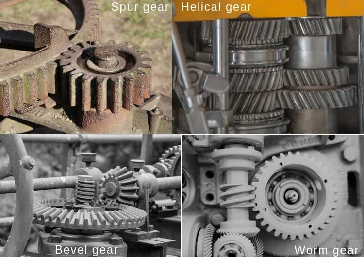
Gears can be classified into four basic groups—spur gear, helical gear, bevel gear and worm gear. Each of these gears has specific features and can offer certain benefits over others. A spur gear is the simplest one that is used to transmit motion and power between parallel driver and driven shafts. It has straight teeth parallel to the gear axis. Another similar gear, called helical gear, is also used for parallel shafts; however, its teeth are cut in the form of a helix over the cylindrical blank. On the other hand, bevel gear is used for intersecting shafts, which may or may not be perpendicular. It may have teeth along the gear axis (straight teeth bevel gear) or in spiral form (spiral teeth bevel gear). The worm gear is used for perpendicular but non-intersecting shafts.

Although both spur gear and helical gear are meant for parallel shafts, each has different teeth orientation and is suitable for different applications. In case of spur gears, teeth of mating gears come in sudden contact. Thus the tooth experiences impact or shock loading. It causes vibration and also reduces service life of the gear. Helical form of teeth can eliminate this problem. In two mating helical gears, teeth come in contact gradually and thus it is free from impact or shock loading. It can carry comparatively higher load. It also offers higher speed reduction. Contrary to spur gear that imposes only radial load, helical gear imposes both radial and axial loads on the bearings. Various differences between spur gear and helical gear are given below in table format.
Table: Differences between spur gear and helical gear
| Spur Gear | Helical Gear |
|---|---|
| In spur gear, the teeth are parallel to the axis of the gear. | In helical gear, teeth are inclined at an angle (called helix angle) with the gear axis. |
| Spur gear imposes only radial load on bearings. | Helical gear imposes radial load and axial thrust load on bearings. |
| Radial bearings that can handle radial load only can be employed here. | Bearings that can handle both radial and axial load must be employed here. |
| Spur gear can be used for parallel shafts only. | Helical gears can be used for parallel shafts or crossed shafts. |
| At the time of engagement, entire face of the tooth comes in contact with the mating tooth. | Here engagement initiates with a point on tooth face and gradually extends across the tooth. |
| Mating teeth are subjected to impact loading. | Load on the mating teeth builds up gradually. |
| Sudden application of load increases vibration, especially in high speed condition. | Gradual loading on teeth minimizes vibration. |
| Spur gear produces noticeable noise due to sudden loading and vibration. | Operation of helical gear is noise free, even at high speed. |
| Teeth of the spur gear can be cut easily as it requires only two dimensional motion. | Making teeth for helical gear is comparatively difficult as it requires three dimensional motion. |
Configuration of gear teeth: Apparent difference between spur gear and helical gear is the form of their teeth. Spur gear has straight teeth that are parallel to the axis of the gear. It is worth mentioning that straight bevel gears also have straight teeth orientated along the gear axis but they are not parallel to the gear axis (they are inclined and thus intersecting). As the name suggests, helical gear has teeth in helix form that are cut on the pitch cylinder. A helical gear can have either left hand helix or right hand helix. Helix angle can vary form one gear to another. Typically, it lies in between 15 – 25°; however, a higher helix angle (up to 45°) can be employed for double helical or herringbone gears.
Nature of load and corresponding bearings: During mating of two gears, the bearings experience torque and forces, which are ultimately transferred to the ground. Direction and intensity of such force vary based on the speed of rotation and teeth configuration. Since some bearings can efficiently handle only radial load, some can handle only thrust load and few can handle both loads, so suitable bearing is required to select based on nature and intensity of such forces. Because of the straight teeth, spur gears impose only radial load on the bearings. Thus a cheaper cylindrical roller bearing can be used. On the other hand, helical gears impose significant radial load and thrust load on the bearings. So deep groove ball bearings, angular contact bearings and taper roller bearing can be employed as these bearings can handle both axial and radial loads.
Orientation of driver and driven shafts: One basic advantage of gear drive over other mechanical drives (like belt or chain drive) is its possibility to use for non-parallel shafts. However, several types of gear are suitable for varying orientations of driver and driven shafts. Both spur gear and helical gears are overwhelmingly used for parallel shafts; whereas, bevel gears can be used for intersecting shafts and worm gear can be used for perpendicular non-intersecting shafts. There exists a particular type of helical gear, called crossed helical gear, which can be employed for transmitting power between perpendicular shafts. This is quite similar to worm gear; however, crossed helical gear cannot provide high velocity reduction. Typically, it is suitable for 1:1 to 1:2 speed ratio (as compared to 1:15 to 1:100 in worm gear). Its application is also limited because of many limitations.
Contact scenario between mating teeth: Spur gears have straight teeth parallel to gear axis. Two mating gears are also mounted in parallel shafts. Thus teeth of two mating spur gears come in sudden contact and the contact is always a line of length equals to teeth face width. On the contrary, helical gears have helical teeth and they are mounted on parallel shafts. So teeth of two mating helical gears come in gradual contact. Their engagement starts with a point and becomes a line and then gradually disengages as a point. So contact length does not remain constant.
Impact load, vibration and noise: Since teeth of two mating spur gears comes in sudden contact, so they experience a shock or impact load. This also produces significant vibration and noise, which sometimes impose limit on maximum permissible speed of operation. On the contrary, gradual contact between mating teeth results a gradual load on the teeth and lower vibration and noise. Thus helical gears can be employed at higher speed without much problem.
Cutting gear teeth: Cutting straight teeth is comparatively easier than cutting helical teeth. Gear milling or gear hobbing can be used to cut teeth of spur and helical gears. In milling, only two simultaneous motions are desired to cut teeth of spur gears; however, three simultaneous motions are required for cutting teeth of helical gear.
Scientific comparison among spur gear and helical gear is presented in this article. The author also suggests you to go through the following references for better understanding of the topic.
- Design of Machine Elements by V. B. Bhandari (Fourth edition; McGraw Hill Education).
- Machine Design by R. L. Norton (Fifth edition; Pearson Education).
- A Textbook of Machine Design by R. S. Khurmi and J. K. Gupta (S. Chand; 2014).


